Switch Mode Power Supply (SMPS): How It Works & Uses
Table of Contents
Working Principle of Switch Mode Power Supply
Structure of Switching Mode Power Supply
What is the purpose of SMPS?
Design of SMPS
Things to note
SMPS Topologies
Conclusion
Switched Mode Power Supply (SMPS) is a technology that takes power efficiency and regulation to a new level. Since power electronics have gradually become the core of modern life, the role of switch mode power supply has become more and more important.
Working Principle of Switch Mode Power Supply
Switch mode power supply improves the efficiency of power supply by converting the power frequency. Unlike linear power supply, SMPS quickly switches between on and off states during operation, so that energy can be effectively managed through energy storage elements such as inductors and capacitors.
1. Input Rectification and Filtering
The input of SMPS is usually AC power. The input end first converts AC power into DC power through a rectifier. The rectifier usually uses a diode bridge circuit to achieve full-wave rectification. The DC power generated at this stage often contains a lot of fluctuations, so it needs to be filtered out by a filter to remove the AC component and make it smoother.
2. High-frequency switching
The rectified DC power enters the high-frequency switching stage. The core here is the power switching device (such as MOSFET or IGBT), which turns on and off quickly at a high frequency (usually tens to hundreds of kilohertz). This high-frequency switching operation is the reason why SMPS got its name.
3. Energy storage and transfer
The operation of high-frequency switching decomposes DC power into high-frequency pulse signals, which are transferred through transformers for energy. The transformer is not only used for voltage conversion, but also provides electrical isolation between input and output. Energy storage elements (such as inductors and capacitors) are responsible for storing and releasing energy between high-frequency pulses, thereby achieving voltage regulation.
4. Output rectification and filtering
On the secondary side of the transformer, the pulse signal is converted into DC power through a rectifier circuit, and then filtered to eliminate ripples, making the output voltage more stable. According to specific design requirements, SMPS can output different voltage levels to meet the needs of various devices.
5. Feedback control
In order to ensure the stability of the output voltage, SMPS usually contains a feedback control circuit. The output voltage is monitored and compared with a reference voltage. If the output voltage deviates from the predetermined value, the control circuit adjusts the switching frequency or duty cycle to correct the deviation of the output voltage.
Structure of Switching Mode Power Supply
The structure of SMPS varies depending on its application scenario, but generally includes the following key parts:
Rectification and filtering circuit: used to convert AC power into DC power and smooth voltage fluctuations.
Switching circuit: includes power switching devices and drive circuits to achieve high-frequency switching operations.
Transformer: used for energy transfer and electrical isolation.
Output rectification and filtering circuit: converts the high-frequency pulses output by the transformer into stable DC power.
Feedback and control circuit: used to maintain the stability of the output voltage.
What is the purpose of SMPS?
Most electronic DC loads, such as microprocessors, microcontrollers, LEDs, transistors, integrated circuits (ICs), and motors, are usually powered by standard power supplies such as batteries. However, batteries often face the problem of over- or under-voltage. Therefore, SMPS provides a stable DC output.
SMPS is a versatile power supply because different topologies can be selected depending on the type of application, such as step-up (Boost), step-down (Buck), and power supplies with input and output isolation.
Speaking of the main advantages of SMPS, a well-designed SMPS can be as efficient as 90% or even higher. In contrast, the efficiency of a linear regulated power supply depends on the voltage drop across the pass transistor. For example, suppose we have a 3V lithium battery that needs to be stepped down to 1.8V to provide 100mA of current. In this case, the power wasted as heat in the transistor is 0.12W, making the power supply efficiency only 40%.
SMPS integrated circuits have almost all the features of discrete SMPS designs, allowing engineers to design custom projects.
Design of SMPS
Compared to linear regulated power supplies, the design of a switching power supply (SMPS) is more complex, but this complexity brings many advantages: it can provide stable, controllable DC power in an efficient manner and output more power within a given physical specification (size, weight, and cost).
The following figure shows a simplified block diagram of an SMPS that converts AC input to regulated DC.
Although there are many different types of SMPS designs, their structures are generally similar. The main types of SMPS designs include:
AC to DC: The input is AC power and the output is regulated DC.
DC-DC boost converter: The input DC voltage is stepped up and the output voltage is greater than the input voltage.
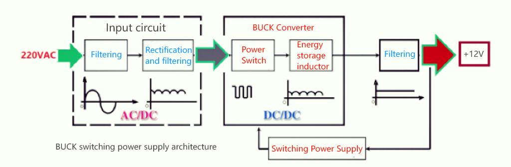
DC-DC buck converter: The input DC voltage is stepped down and the output voltage is less than or equal to the input voltage.
In DC to DC SMPS systems, the input is usually provided by a battery, so boost and buck converter circuits are often used in battery-powered systems.
The above SMPS design represents a typical AC to DC converter. Let's look at the basic working principle of this SMPS design. The input AC power is converted to high-voltage DC by rectification and filtering circuits.
This high-voltage DC is fed into high-speed switching elements, such as power MOSFETs, and the output is high-frequency and high-voltage pulsating AC, which enters a high-frequency step-down transformer.
The transformer outputs a low-voltage AC signal, which is then rectified and filtered to obtain low-voltage DC.
Things to note
The common feature of any SMPS design is the conversion of input AC to high voltage DC, which is then converted to high frequency, high voltage square wave AC. High frequency electronic switches (such as MOSFETs) and square wave oscillators are responsible for converting DC to high frequency AC. The same principle is used in square wave inverters.
By converting the input AC or DC (after rectification and filtering) to high frequency AC, the size and cost of components such as inductors, transformers, and capacitors can be reduced, making them smaller and more economical.
Since the high frequency AC signal generated by the switch is a square wave, the output voltage can be regulated by pulse width modulation (PWM). The voltage is fed back to the control circuit (controlling the PWM) through an isolation circuit. This feedback mechanism changes the PWM duty cycle of the oscillator, thereby accurately regulating the output voltage and avoiding overvoltage.
Overcurrent protection is achieved by comparing the sampled current of the high frequency AC (the signal after the switch) with the reference current and passing it to the control circuit.
In addition, the output DC is completely isolated from the input power supply, and even the feedback signal is isolated by an optocoupler.
The use of square wave driven switching transistors (MOSFETs) ensures low power dissipation compared to the series pass transistor operation mode in linear regulated power supplies.
However, due to the presence of high frequency AC signals in SMPS, high frequency harmonics may cause RF interference.
SMPS Topologies
In the previous section, we looked at the basic design of a switched mode power supply (SMPS). Now let’s look at the different types or topologies of SMPS. The circuit topologies of switched mode power supplies or SMPS are classified into two types: non-isolated converters and isolated converters.
A non-isolated converter is an SMPS topology where the switching circuit is not isolated from the output and both share a common terminal. The three basic and important types of non-isolated SMPS are:
Buck converter
Boost converter
Buck-boost converter
There are other non-isolated SMPS designs like switched capacitor, Cuk converter and SEPIC converter, but these three are particularly important. They are the simplest SMPS designs and use a single inductor as the energy storage element and two switches, one of which is an active switch (transistor - power MOSFET) and the other can be a diode.
The output voltage can be higher (step-up) or lower (step-down) and is controlled by the duty cycle of the high-frequency square wave (applied to the switch). A major disadvantage of non-isolated topologies is that the switching efficiency decreases as the duty cycle decreases. Therefore, isolated topologies are more suitable for larger voltage changes.
The isolation topology in SMPS uses a transformer as an isolator between the switching element and the output. Depending on the turns ratio of the transformer, the output voltage can be higher or lower than the input voltage. Transformer-based SMPS topologies can be designed with multiple output voltages by using multiple windings on the transformer.
The energy storage element can be the secondary winding of the transformer or a separate inductor. Two important SMPS converters based on isolation topologies are:
Flyback converter
Forward converter
Other commonly used isolated SMPS topologies include half-bridge, full-bridge, push-pull, semi-forward, isolated Cuk, etc.
Conclusion
In general, the switching power supply (SMPS) provides a reliable power supply solution for modern electronic devices through its efficient power conversion and diverse circuit topologies. Despite its complex design, its advantages in high efficiency and miniaturization make it an ideal choice for computers, communication equipment and various industrial applications. As technology advances, the design and application of SMPS will continue to evolve, providing more possibilities for future power electronic devices.